HSGQ-QSFP28-DAC:
· 4-channel full-duplex passive copper cable
· Data rate up to 100Gbps (4x 25Gbps)
· SFF-8665 compliant QSFP28 connectors
· SFF-8636 compliant I2C management interface
| Quantity: | |
|---|---|


HSGQ’s The 100G QSFP28 passive cable assembly products, based on 4 x25G or 4 x28G structure, the product can well satisfy the next generation 100G switches, servers, routers and other products of application requirements.QSFP28 cable adopts optimized design to reduce crosstalk and insertion loss, excellent signal integrity, fully conforms to the next generation 100G Ethernet and Infiniband EDR standards.
Features
● 4-channel full-duplex passive copper cable
● Data rate up to 100Gbps (4x 25Gbps)
● SFF-8665 compliant QSFP28 connectors
● SFF-8636 compliant I2C management interface
● IEEE 802.3bj 100GBASE-CR4 compliant
● Copper link length up to 5m (passive limiting)
● Hot Pluggable
● Low power consumption
● Excellent signal integrity, low insertion loss and low crosstalk
● Operating case temperature range: 0°C to +70°C
● Single 3.3V supply voltage
● ROHS compliant
Applications
● 100G Ethernet 100GBASE-CR4
● InfiniBand 4x EDR
● SAS, servers, hubs, switches and routers
● Data Center
Recommended Operating Conditions

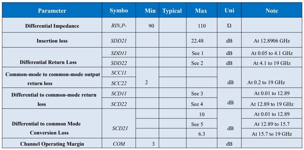
High Speed Characteristics

Notes:
1. Reflection Coefficient given by equation SDD11(dB) < 16.5 - 2 × SQRT(f ), with f in GHz
2. Reflection Coefficient given by equation SDD11(dB) < 10.66 - 14 × log10(f/5.5), with f in GHz
3. Reflection Coefficient given by equation SCD11(dB) < 22 - (20/25.78)*f, with f inGHz
4. Reflection Coefficient given by equation SCD11(dB) < 15 - (6/25.78)*f, with f in GHz
5. Reflection Coefficient given by equation SCD21(dB) < 27 - (29/22)*f, with f in GHz
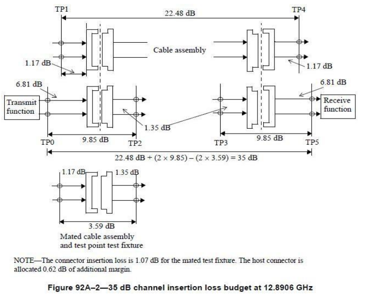
Channel insertion loss budget

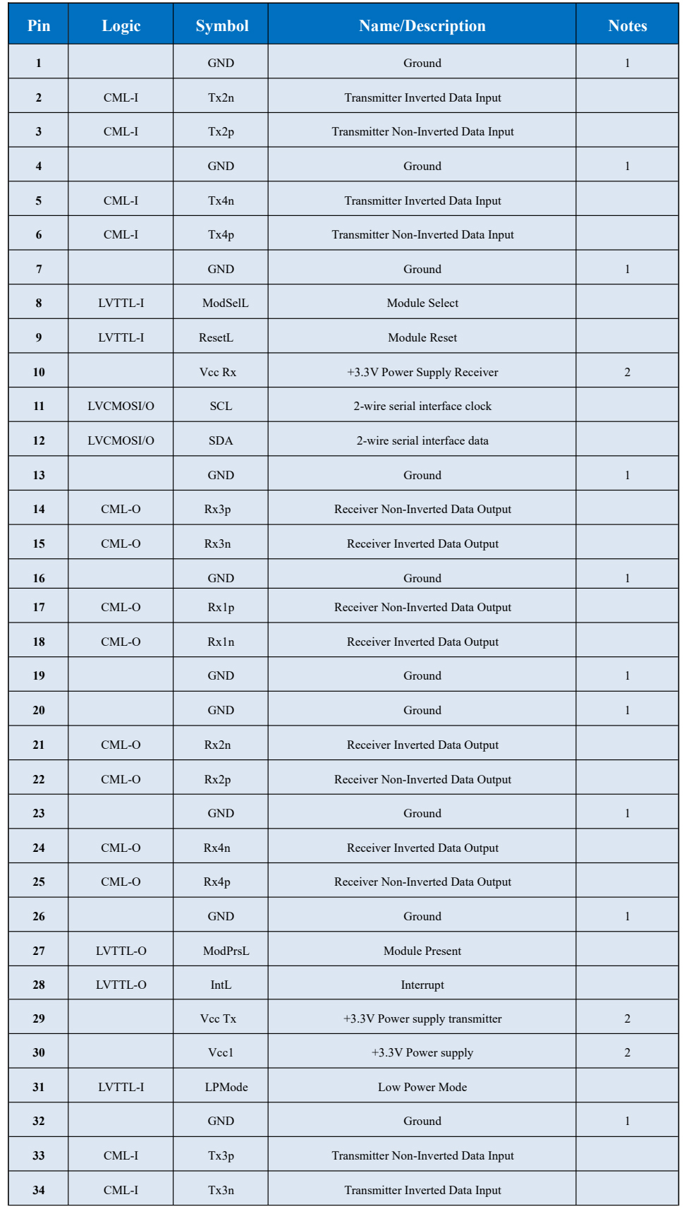
Pin Descriptions

Note 1: GND is the symbol for signal and supply (power) common for the QSFP+ module. All are common within the QSFP+ module and all module voltages are referenced to this potential unless otherwise noted. Connect these directly to the host board signal-common ground plane.
Note 2: Vcc Rx, Vcc1 and Vcc Tx are the receiver and transmitter power supplies and shall be applied concurrently. Requirements defined for the host side of the Host Edge Card Connector are listed in Table 6. Recommended host board power supply filtering is shown in Figure 4. Vcc Rx Vcc1 and Vcc Tx may be internally connected within the QSFP+ module in any combination. The connector pins are each rated for a maximum current of 500mA.
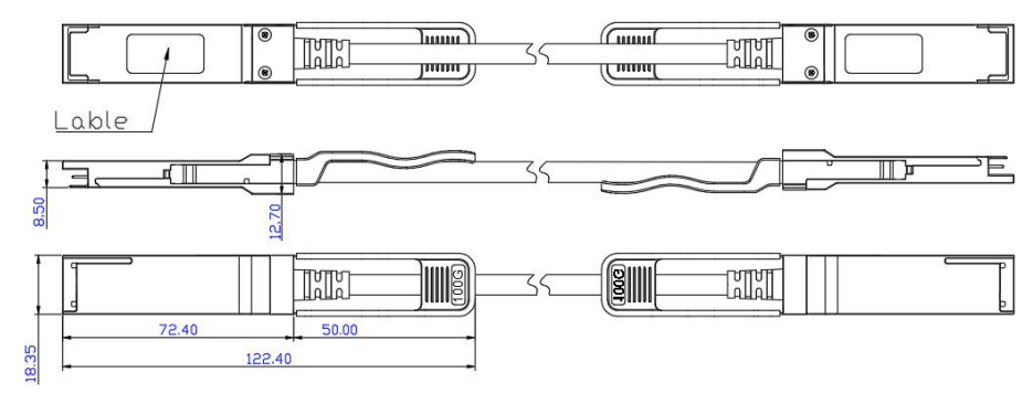
Mechanical Dimensions

Ordering information

Note: You can be customized diameter and distance.
Important Notice
Performance figures, data and any illustrative material provided in this data sheet are typical and must be specifically confirmed in writing by company before they become applicable to any particular order or contract. In accordance with company policy of continuous improvement specifications may change without notice. The publication of information in this data sheet does not imply freedom from patent or other protective rights of company or others. Further details are available from any company sales representative.